How electric motor fail and what we can do for it ?

Electric motor is used everywhere in industry and in term of technology,it is complex , sometimes making it a challenge to keep it running at peak performance.
Before motor fails we can do many things to suppress eventual failure or heavy damages. There are different reasons given below for failure of motor.

motor failure


1.Power Quality 

  • Transient voltage
  • Voltage Imbalance
  • Harmonic Distortion 

2.Variable Frequency Drive

  • Sigma current
  • Reflections on drive output PWM signals
  • Operational overload

3.Mechanical 

  • Misalignment 
  • Shaft imbalance
  • Shaft looseness

4.Improper Installation Factor 

  • Soft foot 
  • Shaft voltage
Here below we discuss about all factors in brief 

Power Quality

  • Transient 
Transient voltage can come from a number of sources either inside or outside of the plant. Adjacent loads turning on/off, power factor correction capacitor banks or even distant weather can generate transient voltage on distribution systems. These transients, which vary in amplitude and frequency,can cause insulation breakdown in motor windings.
Transient may appear on control cables that don't necessarily cause equipment damage directly,but may disrupt operations.

  • Voltage Imbalance 
Three phase distribution systems often serve single phase loads, An imbalance in impedance or load distribution can contribute to imbalance across all three of the phases.
  Please check voltage of each phase by using multimeter.


  • Harmonic Distortion 
Harmonic are any unwanted additional source of high frequency AC voltages or currents supplying energy to motor windings.
These looses dissipate in the form of heat, which, over time, will deteriorate the insulation capability of the windings.some harmonic distortion of the current is normal on any part of the system serving electronic loads.
To start investigating harmonic distortion, use a power quality analyzer to monitor electrical current levels & temperatures at transformers to be sure that they are not overstressed.   
harmonic

    Variable Frequency Drive

    • Sigma Current
    Sigma currents are essentially stray currents that circulate in a system. The sigma currents are created as a result of the signal frequency, voltage level, capacitance and inductance in conductors.These circulating currents can find their way through protective earth system causing nuisance tripping or in some cases excess heat in windings.
    Sigma current find in motor cable.
    The sum of the three currents would equal to zero. means the return current from the drive would be equal to the current to the drive. sigma current can also be understood as asymmetrical signals in multiple conductors that can capacitively couple currents into the ground conductor.


    • Reflections  on drive output  PWM singals 

    VFD employ a pulse width modulation PWM technique  to control the output voltage and frequency to a motor. Reflections are generated when there is an impedance mismatch between the source and load. Impedance mismatch can occur as a result of improper installation, improper component selection or equipment degradation over time, In a motor drive circuit, the peak of the reflection could be as high as the DC bus voltage level.

    • Operational Overload
    When motor is overloaded it draws excessive heat, over current and insufficient torque.
    Motor component which are bearings, motor windings, and other components may be working fine, but the motor will continue to run hot.  30% motor fail because of overloading.

    The Worst Type Of Three Phase Faults (And Why It Happens)

    When three phase fault occur

    In a three phase power system, the type of faults that can occur are classified by the combination of conductors or buses that are faulted together.In addition, faults may be classified as either bolted faults or faults that occur through some impedance such as an arc.  


    Four types of Three Phase Faults

    1. Three Phase bolted faults
    2. Bolted line to line faults
    3. Line to line to ground faults
    4. Line to ground faults

    1. Three Phase Bolted Faults
    A three phase bolted fault describes the condition where the three conductors are physically held together with zero impedance between them, just as if they were  bolted together. For balanced symmetrical system, the fault current magnitude is balanced equally within the three phase.

    While this type of fault does not occur frequently, its results are used for protective device selection, because this fault type generally yields the maximum short circuit current value.
    2. Bolted Line to line Faults
    Bolted line to line faults are more common than three phse faults and have fault current that are approximately 87% of the three phase bolted fault current.

    3. Line to line to Ground Faults
    Line to line to ground faults are typically line to ground faults that have escalated to include a second phase conductor. This is an unbalanced fault. The magnitudes of double line to ground fault currents are usually greater than those of line to line faults, but are less than those three phase faults.
    4. Line to Ground Faults
    Line to ground faults are most common type of faults and are usually the lease disturbing to the system. The current in the faulted phase can range from near zero to a value slightly greater than the bolted three phase fault current. 


    18 Initial Checks Of Electrical Installations Every Electrician MUST Perform

    electrical installations

    Testing of Electrical Installation 

    Before any testing of low voltage electrical installations (and equipment) is carried out, a detailed physical inspection must be made to ensure that everything is:
    1. To a relevant National or Harmonized European Standard
    2. Erected/installed in compliance with the IEE Regulations 
    3. Not damaged in such a way that it could cause danger

    General Testing Checklist

    1.Connections of Conductors
    Are terminations electrically and mechanically sound ? Is installation and sheathing removed only to a minimum to allow satisfactory termination ?

    2.Identification of Conductors
    Are conductors correctly identified in accordance with the regulations?
    identification of conductors

    3.Routing of Cables
    Are cables installed such that account is taken of external influences, such as mechanical damage, corrosion and heat?

    4.Conductor Selection
    Are conductors selected for current carrying capacity and voltage drop in accordance with the design?

    5.Connection of single pole device
    Are single pole protective and switching devices connected in the line conductor only?
    connection of single pole device

    6.Accessories and equipment
    Are all accessories and items of equipment correctly connected?

    7.Thermal effects
    Are fire barriers present where required and protection against thermal effects provided ?

    8. Protection against shock
    What methods have been used to provide protection against electrical shock ?

    9.Mutual detrimental influence
    Are wiring systems installed so that they can have no harmful effect on non-electrical system or so that system of different currents or voltages are segregated where necessary ?

    Regular Motor Maintenance To Avoid Failure

    Motor Maintenance

    A well carefully designed motor maintenance program, when correctly used, can be summed up as
    1.Preventive maintenance
    2.Predictive maintenance
    3.Reactive maintenance

    Inspection cycle depend upon the type of motor and the conditions under which it operates.

    Motors need maintenance regularly in order to avoid failure and prolong their lifespan. Generally speaking, motors and motor parts should be maintained and tested at every 6 months.

    1.Preventive maintenance
    The objective of this kind of maintenance is to prevent operating problems and make sure that the motor continuously provides a reliable operation usually, preventive maintenance is a scheduled part of maintenance a whole system.
       

    2.Predictive maintenance
    The objective of this kind of motor maintenance is to ensure that the right kind of maintenance is carried out at the right time. In order to define these two parameters, it is necessary to monitor the motor operation regularly and thereby detect problems before they actually occur.


    3.Reactive maintenance
    The main objective of this kind of maintenance is to repair and replace the motor when a failure occurs. Reactive maintenance or breakdown maintenance as it is referred to as well, does not imply any regular service or tests.

    The Basics Of Molded Case Circuit Breakers You MUST Know

    Molded Case Circuit Breakers (MCCB)

    Molded case circuit breakers are interrupting devices with self contained, current responsive elements. These breakers are assembled as an integral unit in a supported and enclosed housing of insulating material.


    Depending on the amount of protection required, these breakers can sense internally and then clear under voltage, over current, and short circuit conditions.

    Some tripping elements are also externally accessible through control wiring, and other circuit protection can be added. Breakers may rely solely on outside information to perform their prime function. Several trip units may be available for a particular frame size. A specific assembled breaker may have a lower continuous current rating than the current designation of the frame manufacturers.


    Contacts often begin to part during the first cycle of a fault. The current breaker must be capable of interrupting the maximum allowable first cycle asymmetrical current. The operating mechanism provides a means of opening and closing the toggle mechanism of quick-make/ quick- break type contacts.(Snap open or closed independent of the speed of handle movement).


    Molded case circuit breakers use in restricted to low voltage and medium voltage system 

    MCCB Trip Elements

    Trip elements trip the operating mechanism of a circuit breaker during either a prolonged overload or short circuit currnent. Some molded case circuit breakers have a screwdriver slot located on the front of the trip unit used for adjusting sensitivity.

    The maximum setting is established by protection of the minimum conductor size in the circuit.

    Instantaneous Magnetic Trip
    Magnetic trip work by using an electromagnet in series with the load current. When the current. When  the current reaches the set point, the electromagnet instantaneously trips.This type of trip commonly found in low voltage breakers.

    Thermal Trip
    Considered the industry standard, these trip elements work using a bimetal heated by the load current.When overheated, indicating an overload, the bimetal will detect, which causes the operating mechanism to trip.

    Thermal Magnetic Trip
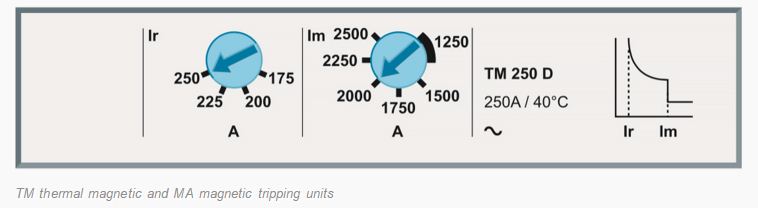
    A thermal magnetic trip, in addition to provide short circuit protection, guards against long- term current overload existing longer then roughly 10 seconds. Because bimetal deection is dependent on current and time, the thermal unit provides long-time delay for light overloads and fast response for heavy overloads.


    Questions to help in preparation about Interview !!!


    At the  eve of interview of any company we always have a fear of being rejected or what they ask me in interview.
    Here are some of questions related to electrical automation engineering for job interview.

    Q-1.  Tell me about your self.
    Ans-  I am ____ from _____ .
              I have __ year of experience of it field.
              My highest qualification is _______from ______university.
              In my family i have _____brothers or sisters_____.
              My hobby is _______.
              That all  about me sir.

    Q-2    What experience do you have in automation field ? 
    Ans-   Hopefully if you're applying for this position you have bags of related experience, and if that's the case you should mention it all. But if you're switching careers or trying something a little              different, your experience may initially not look like it's matching up. That's when you need a              little honest creativity to match the experiences required with the once you have. People skills            are people skills after all, you just need to show how costumer service skills can apply to                      internal management positions, so on.  

    Q-3  What is your greatest weakness ?
    Ans - This is challenging question -- as if you have no weaknesses you are obviously lying! Be           realistic and mention a small work related flaw. Many people will suggest answering this using         positive trait disguised as a flaw such as " I am a perfectionist. "  I would advocate a certain                degree of honesty and list a true weakness. Emphasize what you've done to overcome it and                 improve. This question is all about how you perceive and evaluate yourself.

    Q-4 What challenges are you looking for in this position ?
    Ans- The best way to answer question about the challenges you are seeking is to discuss how you       would like to be able to effective utilize your skills and experience if you were hired for this job.

    Q-5 What do you know about us ?
    Ans- Follow these easy research tips before your next job interview:
            1. Visit company website, look in the "about us".  
            2. Visit the company's linkedin page to view information.
            3. Also read present news about company in " Press release section".


    Where Do Electrical Faults Occur The Most?

    Causes of electrical faults

    A fault is not a natural occurrence. it is an unplanned event which occurs unexpectedly. Electrical faults in an electrical installation or piece of equipment may be caused by

    Negligence - that is lack of proper care and attention

    Misuse - that is not using the equipment properly or correctly

    Abuse - that is deliberate ill treatment of the equipment


    By picture presentation we describe


    7 Possible points where electrical faults occur 


    Point 1- Fault occur in wiring system

    All cable connections must be made mechanically and electrically secure . They must also remain accessible for future inspection , testing and maintenance


    The only three exception to this rule are when

    1. Underground cables are connected in a compound filled or encapsulated joint.

    2. Floor warming or ceiling warming heating system are connected to a cold tail.

    3. A joint is made by brazing , soldering or compression tool.

    Since they are accessible , cable inter connections are an obvious point of investigation when searching out the cause of a fault.


    Point 2- Electrical faults also occur at cable termination

    Flexible cords are delicate - has the terminal screw been over tightened , thus breaking the connection as the conductors flex or vibrate ?


    Hydrogen Bomb

    In start of 2016 we heard very big news from North Korea about successfully tested Hydrogen Bomb.  It is more dangerous than Atom Bomb.


    Figure below shows H bomb invert er and other discription.


    Raliway Requirement Board (RRB)


    RRB announce vacancies for  following posts for more than 18000 posts across India.

    Filling up online form start on  26/12/2015 to 25/01/2016 only through below link

    All are nontechnical posts.
    1. Commercial Apprentice (CA) - 703 Posts
    2. Traffic Apprentice (TA)- 1645 Posts
    3. Enquiry cum reservation clerk (ECRC) -127 Posts
    4. Goods Guard - 7591 Posts
    5. Junior Account Assistant cum typist (JAA) - 1205 Posts
    6. Senior clerk cum typist (SCT) - 869 Posts
    7. Assistance Station Master (ASM) - 5942 Posts 
    8. Traffic Assistance (TA) - 166 Posts
    9. Senior Time Keeper (STK)- 04 Posts
    Education details - Any graduates can apply .(T&C apply)

    A.C. Drives


    Electrical drives are integral part of industrial and automation processes particularly where precise control of speed of the motor is the prime requirement. In addition , all modern electric trains or locomotive system have been powered by electrical drives . Robotics is another major area where adjustable speed drives offer precise speed and position control.


    What is an electric drive ? why it is needed ?

    A drive operates and controls the speed , torque , direction of moving objects. Drives are generally employed for speed or motion control applications such as machine tools, transportation, robots , fans , etc. The drives used for controlling electric motors are known as electrical drives.

    The drives can be of constant or variable type. The constant speed drives are inefficient for variable speed operations ; in such cases variable speed drives are used to operate the loads at any one of a wide range of speeds.


    Why electric drives are needed ?

    • To achieve high efficiency ; electrical drives enable to use wide range of power , from milliwatts to megawatts for various speed and hence the overall cost of operating the system is reduced.
    • To increase the speed of accuracy of stopping or reversing  operation of motor.
    • To control the starting current.
    • To provide the protection .
    • To establish advance control with variation of parameters like temperature , pressure , level , etc.

    Basic block diagram of AC drive 


    In the above block diagram of an electric drive system , electric motor , power processor , controller , sensors and actual load or apparatus are known as the major components included in the drive.


    Power processors is also called as power modulator which is basically a power electronic converter and is responsible for controlling the power flow to the motor so as to achieve variable speed, reverse and brake operations of the motor . The power electronic converters include AC-AC , AC-DC, DC-AC, converters.


    Instrument Transformers

    Instrument Transformer are used in A.C. system for measurement of electrical quantities like voltage , current, power, energy, P.F. frequency. Instrument transformers are also used with protective relays in power protection of power system.


    Basic function of instrumental transformer is to step down the A.C system voltage & current . The voltage & current level of power system is very high. It is very difficult & costly to design the measuring instruments for measurement of such high level voltage & current. Generally measuring instruments are designed foe 5A & 110 volt.


    There are two types of Instrument Transformer 

    1.  Current Transformer (C.T.)

    2. Potential Transformer (P.T.)


    P.T (Potential Tansformer)


    P.T(Potential Transformer) is used to step down the voltage of power system to low voltage level to make is feasible to be measured by small rating voltmeter 110 or 120 volt. A typical diagram shows in below figure.


    Points to be remembered about P.T

    • Connected in parallel with power circuit.
    • Secondary is connected to volt meter.
    • Secondary works almost in open circuit condition.
    • Primary current depends on secondary burden. 
    • One terminal of secondary is earthed for safty 
    Symbol for transformer.


    Related topic

    C.T (current transformer)

    Home Appliance

    Tube light 


    Circuit diagram of tube light.

    Celling fan  


    Refrigerator  

    The basic principle of refrigeration is simple . You simply pass a colder liquid continuously around the object that is to be cooled. This will take heat from the object.


    It has 4 main components
    • Compressor 


    • Condensor


    • Evaporator


    • Throttling device


    CT (Current Transformer)

    What is CT(Current Transformer) ?

    Instrument Transformer are two types CT(current transformer) and VT(voltage transformer).
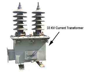
    For stepping down voltages and current for metering and measurement. CT is a type of instrument that design to produce an alternating current in its secondary winding which is proportional to the current being measured in its primary.

    figure of current and voltage transformer.


    Above figure shows how CT is  working .
    CT is just as working as other transformer , 


    from above formula we can find out current in secondary side.
    Is = secondary current
    Ip= primary current 
    Np= no. of turn in primary
    Ns= no. of turn in secondary

    some images of  CT use in field work.


    What ampere current can human body tolerance ?


    DC current effect on  of Human Body 


    AC Current Effect on Human Body


    Current
    Reaction
    1 milliamp
    Just a faint tingle.
    5 milliamps
    Slight shock felt. Disturbing, but not painful. Most people can “let go.” However, strong involuntary movements can cause injuries.
    6-25 milliamps (women)†
    9-30 milliamps (men)
    Painful shock. Muscular control is lost. This is the range where “freezing currents” start. It may not be possible to “let go.”
    50-150 milliamps
    Extremely painful shock, respiratory arrest (breathing stops), severe muscle contractions. Flexor muscles may cause holding on; extensor muscles may cause intense pushing away. Death is possible.
    1,000-4,300 milliamps (1-4.3 amps)
    Ventricular fibrillation (heart pumping action not rhythmic) occurs. Muscles contract; nerve damage occurs. Death is likely.
    10,000 milliamps (10 amps)
    Cardiac arrest and severe burns occur. Death is probable.


    Different Material conductivity and resistivity


    Table of Resistivity and Conductivity of Different Materials at 20°C


    Material
    Resistivity at 20°C
    Conductivity 20°C
    Air
    1.3 × 10¹⁶ to 3.3 × 10¹⁶
    3 × 10-15 to 8 × 10-15
    Aluminum
    2.82 × 10⁻⁸
    3.5 × 10⁷
    Annealed copper
    1.72 × 10⁻⁸
    5.80 × 10⁷
    Calcium
    3.36 × 10⁻⁸
    2.98 × 10⁷
    Carbon (amorphous)
    5 × 10⁻⁴ to 8 × 10⁻⁴
    1.25 to 2 × 10³
    Carbon (diamond)
    1 × 10¹²
    ~10-13
    Carbon (graphite)
    2.5 × 10⁻⁶ to 5.0 × 10⁻⁶ //basal plane
    2 to 3 × 10⁵ //basal plane
    Carbon steel
    -1010
    1.43 × 10⁻⁷
    Constantan
    4.9 × 10⁻⁷
    2.04 × 10⁶
    Copper
    1.68 × 10⁻⁸
    5.96 × 10⁷
    Deionized water
    1.8 × 10⁵
    5.5 × 10⁻⁶
    Drinking water
    2 × 101 to 2 × 10³
    5 × 10⁻⁴ to 5 × 10⁻²
    Fused quartz
    7.5 × 10¹⁷
    1.3 × 10⁻¹⁸
    GaAs
    5 × 10⁻⁷ to 10 × 10-3
    5 × 10⁻⁸ to 103
    Germanium
    4.6 × 10⁻¹
    2.17
    Glass
    10 × 1010 to 10 × 1014
    10-11 to 10-15
    Gold
    2.44 × 10⁻⁸
    4.10 × 10⁷
    Grain oriented electrical steel
    4.60 × 10⁻⁷
    2.17 × 10⁶
    Hard rubber
    1 × 10¹³
    10-14
    Iron
    1.0 × 10⁻⁷
    1.00 × 10⁷
    Lead
    2.2 × 10⁻⁷
    4.55 × 10⁶
    Lithium
    9.28 × 10⁻⁸
    1.08 × 10⁷
    Manganin
    4.82 × 10⁻⁷
    2.07 × 10⁶
    Mercury
    9.8 × 10⁻⁷
    1.02 × 10⁶
    Nichrome
    1.10 × 10⁻⁶
    9.09 × 10⁵
    Nickel
    6.99 × 10⁻⁸
    1.43 × 10⁷
    Paraffin wax
    1 × 10¹⁷
    10-18
    PET
    10 × 1020
    10-21
    Platinum
    1.06 × 10⁻⁷
    9.43 × 10⁶
    Sea water
    2 × 10⁻¹
    4.8
    Silicon
    6.40 × 10²
    1.56 × 10⁻³
    Silver
    1.59 × 10⁻⁸
    6.30 × 10⁷
    Stainless steel
    6.9 × 10⁻⁷
    1.45 × 10⁶
    Sulfur
    1 × 10¹⁵
    10-16
    Teflon
    10 × 1022 to 10 × 1024
    10-25 to 10-23
    Tin
    1.09 × 10⁻⁷
    9.17 × 10⁶
    Titanium
    4.20 × 10⁻⁷
    2.38 × 10⁶
    Tungsten
    5.60 × 10⁻⁸
    1.79 × 10⁷
    Wood (damp)
    1 × 10³ to 4
    10-4 to 10-3
    Wood (oven dry)
    1 × 10¹⁴ to 16
    10-16 to 10-14
    Zinc
    5.90 × 10⁻⁸
    1.69 × 10⁷