How electric motor fail and what we can do for it ?

Electric motor is used everywhere in industry and in term of technology,it is complex , sometimes making it a challenge to keep it running at peak performance.
Before motor fails we can do many things to suppress eventual failure or heavy damages. There are different reasons given below for failure of motor.

motor failure


1.Power Quality 

  • Transient voltage
  • Voltage Imbalance
  • Harmonic Distortion 

2.Variable Frequency Drive

  • Sigma current
  • Reflections on drive output PWM signals
  • Operational overload

3.Mechanical 

  • Misalignment 
  • Shaft imbalance
  • Shaft looseness

4.Improper Installation Factor 

  • Soft foot 
  • Shaft voltage
Here below we discuss about all factors in brief 

Power Quality

  • Transient 
Transient voltage can come from a number of sources either inside or outside of the plant. Adjacent loads turning on/off, power factor correction capacitor banks or even distant weather can generate transient voltage on distribution systems. These transients, which vary in amplitude and frequency,can cause insulation breakdown in motor windings.
Transient may appear on control cables that don't necessarily cause equipment damage directly,but may disrupt operations.

  • Voltage Imbalance 
Three phase distribution systems often serve single phase loads, An imbalance in impedance or load distribution can contribute to imbalance across all three of the phases.
  Please check voltage of each phase by using multimeter.


  • Harmonic Distortion 
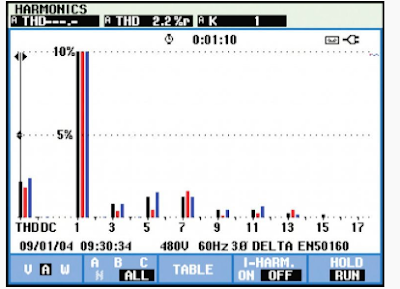
Harmonic are any unwanted additional source of high frequency AC voltages or currents supplying energy to motor windings.
These looses dissipate in the form of heat, which, over time, will deteriorate the insulation capability of the windings.some harmonic distortion of the current is normal on any part of the system serving electronic loads.
To start investigating harmonic distortion, use a power quality analyzer to monitor electrical current levels & temperatures at transformers to be sure that they are not overstressed.   
harmonic

    Variable Frequency Drive

    • Sigma Current
    Sigma currents are essentially stray currents that circulate in a system. The sigma currents are created as a result of the signal frequency, voltage level, capacitance and inductance in conductors.These circulating currents can find their way through protective earth system causing nuisance tripping or in some cases excess heat in windings.
    Sigma current find in motor cable.
    The sum of the three currents would equal to zero. means the return current from the drive would be equal to the current to the drive. sigma current can also be understood as asymmetrical signals in multiple conductors that can capacitively couple currents into the ground conductor.


    • Reflections  on drive output  PWM singals 

    VFD employ a pulse width modulation PWM technique  to control the output voltage and frequency to a motor. Reflections are generated when there is an impedance mismatch between the source and load. Impedance mismatch can occur as a result of improper installation, improper component selection or equipment degradation over time, In a motor drive circuit, the peak of the reflection could be as high as the DC bus voltage level.

    • Operational Overload
    When motor is overloaded it draws excessive heat, over current and insufficient torque.
    Motor component which are bearings, motor windings, and other components may be working fine, but the motor will continue to run hot.  30% motor fail because of overloading.

    The Worst Type Of Three Phase Faults (And Why It Happens)

    When three phase fault occur

    In a three phase power system, the type of faults that can occur are classified by the combination of conductors or buses that are faulted together.In addition, faults may be classified as either bolted faults or faults that occur through some impedance such as an arc.  


    Four types of Three Phase Faults

    1. Three Phase bolted faults
    2. Bolted line to line faults
    3. Line to line to ground faults
    4. Line to ground faults

    1. Three Phase Bolted Faults
    A three phase bolted fault describes the condition where the three conductors are physically held together with zero impedance between them, just as if they were  bolted together. For balanced symmetrical system, the fault current magnitude is balanced equally within the three phase.

    While this type of fault does not occur frequently, its results are used for protective device selection, because this fault type generally yields the maximum short circuit current value.
    2. Bolted Line to line Faults
    Bolted line to line faults are more common than three phse faults and have fault current that are approximately 87% of the three phase bolted fault current.

    3. Line to line to Ground Faults
    Line to line to ground faults are typically line to ground faults that have escalated to include a second phase conductor. This is an unbalanced fault. The magnitudes of double line to ground fault currents are usually greater than those of line to line faults, but are less than those three phase faults.
    4. Line to Ground Faults
    Line to ground faults are most common type of faults and are usually the lease disturbing to the system. The current in the faulted phase can range from near zero to a value slightly greater than the bolted three phase fault current.