Transformer

     Transformer

What is a transformer ?

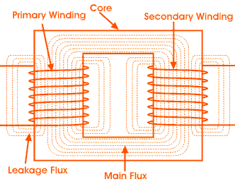
Transformer is  a static device that transform electrical power from one circuit to another with the help of mutual induction in it. It transfer power from one winding to another winding without changing frequency.
1. Primary Winding : It is input of the transformer ,

2. Core : It is a structure of the transformer.

3. Secondary Winding :  Flux which is produced by the primary winding passes through laminated core and reached to the secondary winding. It is also known as output of the transformer.


Sensors

                       Sensors for Industrial Automation

                        Selecting sensor for particular application in industrial automation is a real choice to make .There would be plenty of sensors available in the market , each based on different principles of operation and different level of precision .


    What is the first thing that comes to your mind when you hear the word 'sensor' ? It would most likely be the sense organs that we have eyes, nose, ears, tongue and skin. These are the natural sensors that we have. Based on the sensory organs, if we define sensor, then we can say that it is a device that allows us to sense objects around us, to see them, to smell the odor , to taste eatables, to feel the environment, etc. However .in general terms, a sensor can be define as a device that detects, measures and converts a physical  quantity into a signal that can be read by an observer or an instrument. A sensor allows us to notice things and understand them easily.

The sense organs that we have are considered to be natural sensors and based on these sensors, we have many man made or artificial sensors that allow us to make our life easy day by day . The artificial sensors are hardware components that can allow a device to know its location, surrounding and many more things . These can be either wired or wireless.

Let us discuss these sensors in detail to determine their features and to understand their scope of use.


Introduction to DC Motor

                            Introduction to DC Motor

Principle of DC Motor

This DC or direct current motor works on the principle, when a current carrying conductor is placed in a magnetic field, it experiences a torque and has a tendency to move. This is known as motoring action. If the direction of current in the wire is reversed, the direction of rotation also reverses. When magnetic field and electric field  interact they produce a mechanical force, and based on that the working principle dc motor established.


The direction of rotation of a this motor is given by Fleming's left hand rule, which states that if the index finger, middle finger and thumb of your left hand are extended matually perpendicular to each other and if the index finger represents the direction of magnetic field , middle finger indicates the direction of current, then the thumb represents the direction in which force is experienced by the shaft of the dc motor. Structurally and construction wise a direct current motor is exactly similar to  a dc generator, but electrically it is just the opposite. Here we unlike a generator we supply electrical energy to the input port and derive mechanical energy from the output port. We can represent it by the block diagram shown below.


Here in  a DC motor, the supply voltage E and current I is given to the electrical port or the input port and we derive the mechanical output i.e. torque T and speed w from the mechanical port or output port.

 The input and output variables of the direct current motor are related by the parameter K.
                                       T=K I
 

Power Factor

                                      Power Factor

                              In general power is the capacity to do work. In electrical domain, electrical power is the amount of electrical energy that can be transferred to some other form (heat, light etc) per unit time. Mathematically it is the product of voltage drop across the element and current flowing through it.
                              Considering first the DC circuits, having only DC voltage sources, 
 inductor is like short circuit
capacitor is like open circuit
                                                    in steady state.
Hence the entire circuit behaves as resistive circuit and the entire electrical power is dissipated in the form of heat . Here the voltage and current are in same phase and the total electrical power is given by 
Electrical power = Voltage across the element * Current through the element

 Its unit is Watt = Joule/sec.
Now coming to AC circuits , The inductor stores electrical energy in the form of magnetic energy and capacitor stores electrical energy in the form of electrostatic energy. Neither of them dissipates it. Further there is a phase shift of 90 degree between voltage and current. Hence when we consider the entire circuit consisting of resistor, inductor and capacitor, there exists some phase difference between the source voltage and current. The cosine of this phase difference is called electrical power factor .
    
                   This factor (0<cos<1) represents the fraction of total power that is used to do the useful work.


                 The total power in this case is , Total electrical power = voltage across the element * current through the element. This is called apparent power and its unit is VA (volt amp.)  and it is denoted by S.
                 A fraction of this total electrical power which actually does our useful work is called as active power . It is denoted by P 
P= Active power = Total electrical power cos and its unit is watt .
The other fraction of power is called reactive power .  This does no useful work, but it is required foe the active work to be done. It is denoted by Q and mathematically is given by,

Q= Reactive power = total electrical power sin and its unit is VAR (volt anp reactive)
\
This reactive power oscillates between source and load.


     Mathematically   S2 = P2 + Q2   .    


Three Phase Induction Motor and its Application

       Three Phase Induction Motor and its Application

1. Squirrel Cage Induction Motor 

2. Slip Ring Induction Motor 


1. Squirrel Cage Induction Motor

             Induction motor is also called asynchronous motor as it runs at a speed other than the synchronous speed. Like any other electrical motor, induction motor have two main parts namely rotor and stator,


working principle

The slots of the stator core contain three separate single phase windings. When three currents 120 electrical degrees apart pass through these winding, a rotating magnetic field results. This field travels around the inside of the stator core. The speed of the rotating magnetic field depends on the number of stator poles and the frequency of the power source. This speed is called the synchronous speed and is determined by the formula given below
 
Synchronous speed RPM = 120 * frequency in hertz / No. of poles

S= 120*f / p

S = Synchronous speed 

f = Hertz (frequency)

p = no. of poles per phase 

Single Phase Induction Motor and its Application

                       Induction Motor diagram and Application


1. Split phase induction motor

2. Capacitor start induction motor

3. Capacitor start capacitor run induction motor

4. Shaded pole induction motor


1. Split phase induction motor


  Stator of single phase induction motor is divided into two winding Main winding and Auxiliary winding or Starting winding . A centrifugal switch is connected in series with Starting winding. The purpose of this switch is to disconnect the starting winding from main winding from the main circuit when the motor attains a speed up to 75 to 80 % of the synchronous speed. We know that the running winding is inductive in nature. Our aim is to create the phase difference between the two winding and this is possible if the starting winding carries high resistance.


Application
Split phase motors used ind small grinders, small fan, and blowers, and other low starting torque application with power needs from 1/20 to 1/3 hp .


Induction Motor Working & Types of Induction Motor

Induction Motor 

Under Induction Motor

 One of the most common electrical motor used in most application which is known as induction motor. This motor is also called as asynchronous motor because it runs at a speed less than synchronous speed. In this ,we need to define what is synchronous speed. Synchronous speed is the speed of rotation of the magnetic field in a rotary machine and it depends upon the frequency and no. poles of the machine . An induction motor always runs at a speed less than synchronous speed because the rotating magnetic field which is produced in the stator will generate flux in the rotor which will make the rotor to rotate , but due to the lagging of flux current in the rotor with flux current in the stator, the rotor will never reach to its rotating magnetic field speed i.e. the synchronous speed, There are basically two types of induction motor that depend upon the input supply - 
single phase induction motor 
three phase induction motor 

single phase induction motor is not a self starting motor which we will discuss and three phase induction motor is self starting motor. Now in general we need to give two supply i.e. double excitation to make a machine to rotate .


Working Principle of  Induction Motor

But in induction motor we give one supply, so it is really interesting to know that how it works. It is very simple,from the name itself we can understand that there is induction process occurred.Actually when we are giving the supply to the stator winding, flux will generate in the coil due to flow of current in the coil. Now the rotor winding is arranged in such a way that it becomes short circuited in the rotor itself. The flux from stator  will cut the coil in the rotor and since the rotor coils are short circuited, according to faraday's law of electromagnetic induction current will start flowing in the coil of the rotor. When the current will flow,another flux will generated in the rotor, Now there will be two flux, one is stator flux and another is rotor flux and the rotor flux will be lagging to stator flux,
Due to this, the rotor will feel a torque which will make the rotor to rotate in the direction of rotating magnetic flux. So the speed of the rotor will be depending upon the the ac supply and speed can be controlled by varying the input supply, This is the working principle of an induction motor of either type,

working of wind turbine


Major Parts Of Wind Turbine 

Tower of wind turbine 

Tower is very crucial part of wind turbine that supports all the other parts. It is not only support the parts but raise the wind turbine so that its blades safely clear the ground and so it can reach the stronger winds at higher elevations. The height of tower depends upon the power capacity of wind turbine. Larger turbines usually mounted on tower ranging from 40 mtr to 100 mtr.

Nacelle of wind turbine 

Nacelle is big box that sits on the tower and house all the components in a wind turbine . It houses power converter, shaft,gearbox , generator,turbine controller , cables ,yaw drive.

Rotor blades of wind turbine 

Blades are the mechanical part of wind turbine that converts wind kinetic energy into mechanical energy. When the wind forces the blades to move , it transfers some of its energy to shaft. Blades are shaped like airplane wings blades can be as long as 150 feet.

Shaft of wind  turbine 

The shaft is connected to the rotor . when the rotor spins , the shaft spins as well. In this way the rotor transfers its mechanical energy to shafts which enters to an electrical generator on the other hand .